Case Studies
Turbo Stress
Integrator digs deep inside Matrox Imaging Library (MIL) to inspect turbine blades in aircraft engines
Turbines that are housed in aircraft engines are subjected to pretty tough conditions. They must perform at speeds of 30 thousand rpm in temperatures greater than 800ºC for hours at a time.
The engine manufacturers fully understand that even small surface defects can reduce performance, increase maintenance costs, and reduce the useful life of an aircraft engine. They need to inspect turbine blades very carefully to maintain the efficiency and reliability that the air transport industry requires.
One particular North American manufacturer inspected its blades by hand and human eye. The highly-trained inspectors measured hundreds of features and checked for surface defects at depths in the order of thousandths of an inch. Manual inspection was not only costly in terms of time and labor, but subjective as well. Results were variable and even differed between inspectors. Finally, because manual inspection was so time consuming, there was no systematic inspection of every blade; only a sampling of blades were inspected. Clearly, the manufacturer required an approach that would allow systematic inspections of the blades, save time, and yield consistent and repeatable results.
They approached Orus Integration Inc. (Laval, Quebec) to design a turbine inspection system. Project Manager Louis Dicaire says that early in the project, the development team learned that flexibility, repeatability, and precision were absolutely necessary for success. During development, the Orus engineering team relied on their previous experience - they designed vision-based metrology systems for the Canadian military and aerospace industry. They also worked closely with Genik Automation for part handling and mechanical engineering of the machine.
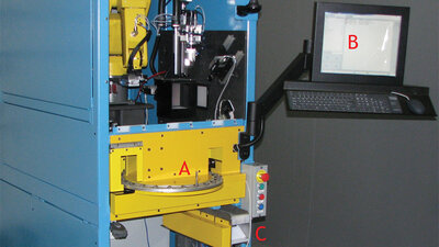
The carousel that holds the parts lies in the vertical center of the INL-1900x2T (A). The Operator Interface and inspection results are displayed on a monitor (B). Non-conforming parts are returned to the operator through the reject chute so they can be re-machined to tolerance (C).
The system
Orus calls the system the INL-1900x2T. A single enclosure houses two stations that perform the inspections. The metrology station features two Basler GigE cameras at 1920 x 1080, each fitted with a large field of view telecentric lens (non-perspective lens), and two collimated LED blue (520nm) lights. The surface inspection station uses four Basler GigE cameras; the resolution of the first camera is 1920 x 1080 for the surface inspection, and the remaining three offer a 640 x 480 resolution for surface inspection of areas that are hard to reach with a single camera. Two CCS diffuse on-axis lights and one CCD diffuse backlight illuminate the surface station. A Fanuc 6-Axis LR Mate 200iC robot and 4U controller and Omron PLC round out the hardware components. The software is based on the Matrox Imaging Library (MIL) 9.0 with Processing Pack 1.
The blade's journey
The INL-1900x2T has three inspection roles to fill: verify several hundred metrology features of the blade, inspect both sides of the turbine blade and other critical surfaces for defects, and validate the part's character markings. The entire inspection procedure takes 15 seconds per part.
To perform a batch inspection, an operator first scans the barcode on the job sheet with a barcode scanner and loads the pocket wheel with the carousel that holds the parts. Then the wheel indexes the first part while a height detector validates its Y position to ensure the part was properly loaded. The robot picks up the part by its blade section and carries it to the metrology station, which is illuminated by the two collimated lights. With the camera's telecentric lenses, and the 4-inch slab of granite to absorb heat and vibrations, the INL-1900x2T has a very stable optical system. "Under these conditions, the contrast of the round sections of really shiny objects appear super sharp," explains Dicaire.
Precision is extremely important in this application. "The robot is very repeatable, but cannot place the blade with the precision that we need, which is smaller than 10 microns," he says. Orus's solution was to rotate the part and acquire the images at high speed. Depending on the feature that needs measuring, the software minimizes or maximizes a specific feature. When an image of a particular reference point, called the datum, matches the original CAD drawing, the software identifies it as the reference image. Then the metrology software measures the part's parallelism, length, radius, angles and other feature. Since there are many datums to optimize, this step is performed more than once. The software records results for hundreds of features and 50 tolerances.
After the software records the metrology results for all of the blade's features, the robot places the blade in a three-pronged gripper that is mounted on a Y-Theta station. The clamp rotates the blade 360º to inspect both sides for surface defects. Then the software verifies the part's character markings: first by stitching together several images to form a complete image and then by performing the OCR algorithms that determine the character.
When the inspections are complete, all the results for the part are logged; all data is available for reporting. If the part passes inspection, the robot puts the part in a "good parts" chute. If a feature has failed, the part is held in the clamp and information is displayed on the screen so the operator knows what to correct on that specific part. Then the gripper releases the part into a reject chute. The wheel turns, indexes the next part and the process repeats for all parts in the carousel.
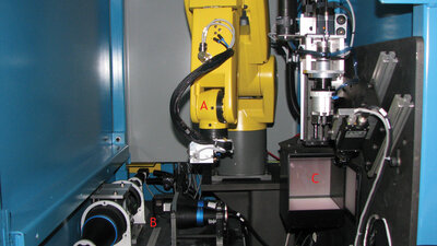
First the robot (A) brings the part to the metrology station where it is subjected to collimated illumination and rotated for image acquisition (B). Then the robot places the part in the gripper of the surface inspection station (C). While the gripper rotates the part, the robot picks up the next one from the carousel. If the part passes inspection, the gripper drops it in the "good part" chute (D); if it fails, the gripper drops it in the reject chute.
MIL power
Orus has used Matrox Imaging Library (MIL) for almost nine years. "This is probably the project where we dug deepest inside the library," says Dicaire. One of the implemented algorithms features an adaptive threshold: the algorithm dynamically locates bright spots in dark areas and dark spots in bright areas. For other operations, the developers at Orus used the GUI interfaces for several MIL modules: OCR, Edge Finder, Geometric Model Finder, and of course Metrology. The metrology software was almost exclusively developed with the GUI so the system could learn the parts. Indeed, the INL-1900x2T's flexibility means the system can accommodate several different parts, even new parts that are still under development. "With the GUIs," explains Dicaire, "we can build a system that lets our clients be more autonomous with the final product. We find that, with the level of complexity of our projects, MIL's ease-of-use, performance, flexibility, and the great support from [Matrox Imaging's] Vision Squad team are the reasons we continue to develop with MIL."
Measuring up to the challenge
Dicaire says that the challenge of designing metrology machines are always the same: repeatability, precision, and linearity. To get the system to return predictable, repeatable results, the software must exhibit fine sub-pixel accuracy; the machine shows +/-3 sigma under 5 microns. Of course, an image is only as good as its lighting, and Dicaire notes that the system requires a stable and high-performance optical system. To achieve the required precision, Orus used a military-grade calibration target to calibrate both cameras at the same time.
Though the INL-1900x2T saves thousands of hours of labor, its main advantage is its ability to perform very complex analyses, while offering a simple interface and a very easy-to-use concept for the operators. "This project uses an array of field-proven technology: robot, axis, vision library. All of this enables the machine to grow and adapt to the client's future needs. Except for the mechanical design, almost all components are off-the-shelf."
"This machine is a mix of technologies that are all dedicated to make the vision system work in optimal conditions," says Dicaire. "It's a great example of what we can do."
For more information contact Media Relations.